Device Manager It provides centralized control of external devices via IP communication using a proprietary protocol.
Between devices that can be controlled are Matrices, GPIO, Serials.
At any time you can view the status of Matrices and GPIO ports.
Configuration
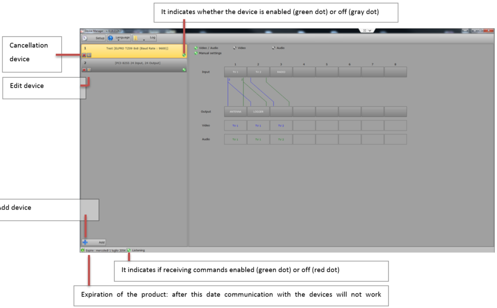
The main screen displays all the devices you want to control and selecting the device will display the status of the GPIO ports or connections for matrices.
The displayed item will be highlighted with a yellow background
It indicates whether the device is enabled (green dot) or off (gray dot)
Video Router
Manual settings: If enabled allows you to perform switching directly from the Device Manager
To perform the switching manually press the button first and then the output of the input
Video / Audio:It indicates that is switched both video and audio
Videos:Indicates that the video is switched only
Audio: Indicates that the audio is switched only
It displays the status of the matrix and to perform switching operations.
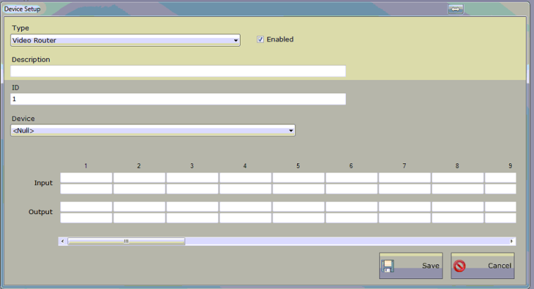
Enabled:It indicates whether communication with the device is enabled
Description:Description of the device
ID: Unique identifier of the device
Device:Type of device selected from those present in the list
Input Output:Label that can be assigned to each device port
Depending on the selected device configuration parameters can be changed:
- Timeout read status (ms):How often re-read device status to be shown on screen
- Wait after write (ms):Minimum waiting time between two switching
- Address: Address for communication with the device
- Port: Door of communication with the device
GPI
Manual settings: If enabled allows you to perform switching directly from the Device Manager
To change the state of an output press the corresponding ball.
The inputs can not be switched manually.

It displays the status of the matrix and to change the status of the output pin.
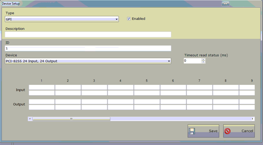
Enabled:It indicates whether communication with the device is enabled
Description:Description of the device
ID: Unique identifier of the device
Device:Type of device selected from those present in the list
Input Output:Label that can be assigned to each device port
Depending on the selected device configuration parameters can be changed:
- Timeout read status (ms):How often re-read device status to be shown on screen
- Wait after write (ms):Minimum waiting time between two switching
- Address: Address for communication with the device
- Port: Door of communication with the device
Serial
It allows you to communicate with the serial
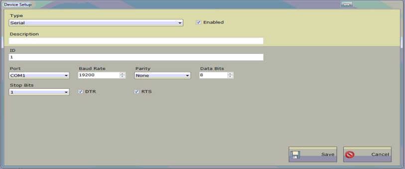
Enabled:It indicates whether communication with the device is enabled
Description:Description of the device
ID: Unique identifier of the device
Port: Serial port with which to communicate
Baud Rate, Parity, Data Bits, Stop Bits, DTR, RTS: Parameters of the serial
TCP / IP, UDP
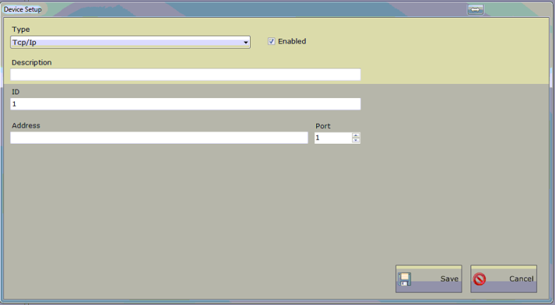
Enabled:It indicates whether communication with the device is enabled
Description:Description of the device
ID: Unique identifier of the device
Address, Port:Address and port to send commands
Application
It performs application every time the command is received
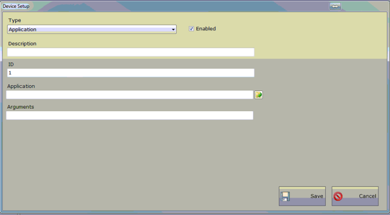
Enabled:It indicates whether communication with the device is enabled
Description:Description of the device
ID: Unique identifier of the device
Application: Application to run
Arguments:Any commands to switch to the application on the command line
Setup
Shared Folder: Folder where information is stored
Shared Folder Main Playout: Backup folder which stores the information
Broadcast address:Broadcast address where you can receive information.
Value 255 indicates that that part of the address is variable, lower values indicate that it is a fixed part (values vary depending on whether the network is class A, B, C).

When you add a device, you can choose the type from those listed:

Depending on the selected device will need to enter more information.